27. Sending TTL triggers
Many pieces of equipment synchronize by exchanging triggers (0/1 bits) on a TTL interface.
A TTL signal is defined as “low” when it is between 0 V and 0.8 V with respect to the ground terminal, and “high” when it is between 2 V and VCC (5 V).
For example, you may need to send a trigger to an EEG or MEG recording machine, or wait for a MRI scanner signaling that it is starting to acquire brain images.
To send or read TTL signals with your computer, you need some extra hardware (unless you have a Raspberry Pi which has a GPIO port).
27.1. Parallel Port
A parallel port has become a rarity these days. It provides a number of Digital (TTL) Input/Ouput lines. The `ParallelPort object in Expryiment <https://docs.expyriment.org/expyriment.io.ParallelPort.html>__ makes it extremely easy to access them.
For example, to swith on and off every second the data lines of the first parallel port:
from time import sleep
from expyriment.io import ParallelPort

pp = ParallelPort('/dev/parport0')

while True:
    pp.set_data(255)
    sleep(1)
    pp.set_data(0)
    sleep(1)
Or to detect any change on any input pin of the parallel ports:
from expyriment import io

pports = [io.ParallelPort('/dev/' + pp)
          for pp in io.ParallelPort.get_available_ports()]

prev_state = []
while True:
  state = str([bin(p.poll()) for p in pports])
  if state != prev_state:
      print(state)
      prev_state = state
Note
Under Linux, you may need to run:
 sudo rmmod lp
 sudo modprobe ppdev

 # to make it permanent
 echo "blacklist lp" > /etc/modprob.d/blacklist_lp.conf


And run http://www.vdwalle.com/Norte/ppdiag.txt to set the adequate permissions
If you do not have the expyriment module, you can just install pyparallel:
pip install pyparallel
Then run in python:
from time import sleep
from parallel import Parallel

pp = Parallel('/dev/parport0')

pp.setData(255)
time.sleep(1)
pp.setData(0)

print(pp.getData())
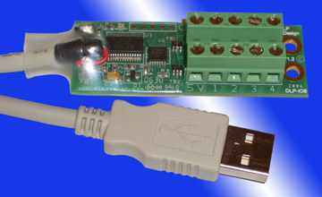
27.2. DLP-IO8-G
The DLP-IO8-G is a USB-TTL device that provides 8 digital lines on which you can read or write. Plugged in USB port, it is seen by the computer as a serial device. Thus, to communicate with it, you simply need to open the relevant serial port and then write to or read from it.
Under Linux, the dlp-OI8-G driver is already present in the kernel. Once
plugged, to determine the serial port it is attached to, type the
command dmesg in a Terminal. You should get something like:
[ 5128.109725] usbcore: registered new interface driver usbserial_generic
[ 5128.109730] usbserial: USB Serial support registered for generic
[ 5128.112142] usbcore: registered new interface driver ftdi_sio
[ 5128.112148] usbserial: USB Serial support registered for FTDI USB Serial Device
[ 5128.112175] ftdi_sio 1-1:1.0: FTDI USB Serial Device converter detected
[ 5128.112190] usb 1-1: Detected FT232RL
[ 5128.113130] usb 1-1: FTDI USB Serial Device converter now attached to ttyUSB0
The last line tells you that the device is at /dev/ttyUSB0.
27.3. Python
To use the device under Python, you need the pyserial module
27.3.1. sending triggers
from serial import Serial

dlp = Serial(port='/dev/ttyUSB0', baudrate=115200)  # open serial port

dlp.write(b'QWERTYUI')  # set all lines to '0'
dlp.write(b'12345678')  # set all lines to '1'
#! /usr/bin/env python3

""" Generate a square wave on pin1 of DLP-IO8-G """

from time import perf_counter
from serial import Serial

dlp = Serial(port='/dev/ttyUSB0', baudrate=115200)  # open serial port
# byte codes to control line 1:
ON1 = b'1'
OFF1 = b'Q'

# number of periods
NPERIODS = 1000

# Timing of the square wave
TIME_HIGH = 0.010   # 10ms pulse
TIME_LOW = 0.090    # send every 100ms
PERIOD = TIME_HIGH + TIME_LOW

onset_times = [ (PERIOD * i) for i in range(NPERIODS) ]

i = 0
while i < NPERIODS:
    if i == 0:
        t0 = perf_counter()

    # wait until the start of the next period
    while perf_counter() - t0 < onset_times[i]:
        None

    dlp.write(ON1)

    # busy wait for 'TIME_HIGH' seconds. This should be more accurate than time.sleep(TIME_HIGH)
    t1 = perf_counter()
    while perf_counter() - t1 < (TIME_HIGH):
        None

    dlp.write(OFF1)
    i = i + 1
    print(f"\r{i:4d}", end='')

time.sleep(TIME_LOW)
print()
print(f'{NPERIODS} periods of {PERIOD} seconds')
print('Total time-elapsed: ' + str(perf_counter() -t0))
dlp.close()         # close the port
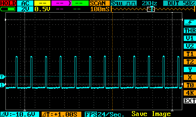
Here is the result on an oscilloscope:
27.4. Reading an input line
import time
import serial
import numpy as np
import matplotlib.pyplot as plt


dlp = serial.Serial(port='/dev/ttyUSB0', baudrate=115200)  # open serial port
print(dlp.name)         # check which port was really used
dlp.write(b'`')  # switch to ascii mode

N = 1000
o = np.zeros(N)  # will store timestamps when the input line is HIGH

i = 0
while i < N:
   dlp.write(b'A')  # request to read
   x = dlp.read(3).decode('utf-8')
   if x[0] == '1':  # the line is HIGH
      o[i] = time.perf_counter()
      i += 1

plt.hist(np.diff(o) * 1000.0)  # plot the deltas between timestamps
27.4.1. Latencies and reliability to measure a time interval
TODO
27.5. Arduino
If you do not have a DLP-IO8-G, another approach is to use an Arduino and program it to send a signal to your PC when it received a trigger. The Leonardo version is recommended as it can be seen as an HID device and it is trivial to program it to send a key press to your computer upon receving a trigger. Thus, you stimulation program just has to wait for a keypress and does not even need to open a serial port.
27.6. Raspberry Pi
You can use gpizero or RPi.GPIO
The RPi.GPIO web page warns that “this module is unsuitable for real-time or timing critical applications. This is because you can not predict when Python will be busy garbage collecting. It also runs under the Linux kernel which is not suitable for real time applications - it is multitasking O/S and another process may be given priority over the CPU, causing jitter in your program. If you are after true real-time performance and predictability, buy yourself an Arduino”
This is true, but nevertheless the Raspberry PI may be sufficient for an application that does not overloard the PC and just need to read or send some sparse triggers. The only way to know is to check for latencies using an external equipment.